Interactive CAD Viewer
Drag to rotate, scroll to zoom, and right-drag (or two-finger drag) to pan.
Initial Concept (Dropped)
Initial Design: Encoder + Game Plan
Early autonomous concept before settling on the final fire-only 3-loop routine.
Start with a fixed launch path to reach a repeatable first shooting location.
Fire an initial burst toward the 16 in / 8 in rings, then reset heading and reposition.
Run one additional scoring pass if timing remained within the autonomous window.
Use a timed fallback path when sensor confidence dropped to keep the routine deterministic.
Initial encoder integration plan (for shooter control and timing gates).
Use the 20 PPR AB hall encoder on the 775 shooter motor for closed-loop RPM control.
Count encoder pulses with interrupts and convert pulse rate to shooter wheel speed.
Gate feed actions so pucks are released only after the shooter reached target speed.
Wheel odometry was considered, then deprioritized because mecanum slip reduced position trust.
Dropped plan: this initial strategy depended on live encoder feedback, but we fried the encoder during
testing, so the final implementation switched to a simpler timed shooter/feed routine.
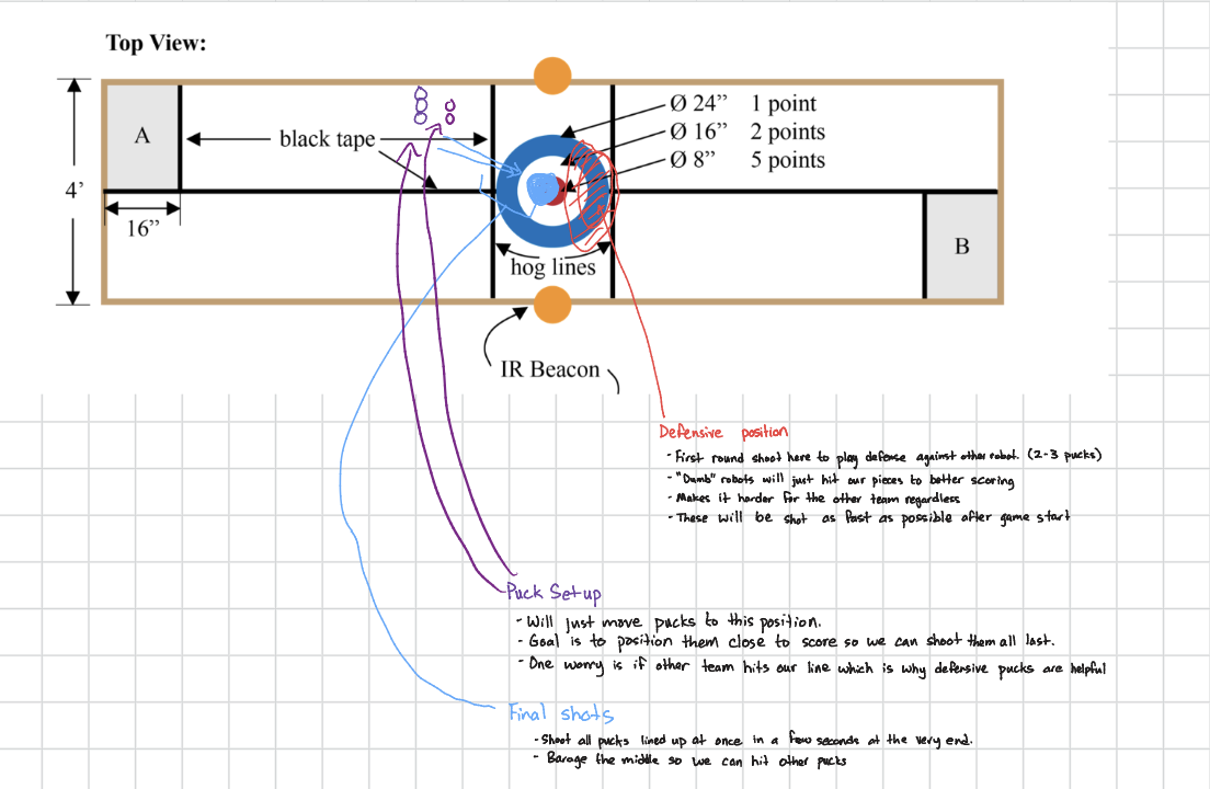
Initial strategy sketch: planned late-match shot sequence and puck setup concept.
Initial drivetrain and autonomy notes: ultrasonic positioning, IMU heading lock, and early state machine.
Design Review Decision and Documentation Bundle
After the initial design review, we committed to a
mecanum + wall-referenced autonomous shooter architecture because it was the fastest path to
reliable points.
Selected because lateral correction and heading hold supported repeatable shot entry angles.
Mechanical complexity was kept moderate so integration could finish before final test windows.
Control plan emphasized deterministic loops over reactive behaviors with high debug cost.
Later, the encoder failure forced a tactical pivot from full closed-loop shooter speed control to timed feed/firing. The
core drive and pose-control architecture remained the same.
Schematics / Wiring Scope
PCA9685 PWM control + motor drivers + ultrasonic sensors + MPU6050 on a shared control stack.
Drawings
initialstrategy.png and
intialdrivetrain.png .
Photos / 3D Model
Interactive CAD above plus downloadable
robot.glb for geometry inspection.
Calculations
Travel-time, loop-budget, and tolerance calculations are documented in the section below.
Final Implemented Design
Final Strategy Overview
The current match strategy is a fire-only autonomous loop : drive to shot position, align, fire
pucks into target rings, reset, and repeat.
All autonomous time is spent on positioning and firing pucks into scoring rings.
Use ultrasonic + IMU to hit the shooting pose reliably each loop.
Spin up shooter, strafe through the shot path, then repeat after a timed reset.
Scoring target zones:
24 in ring: 1 point
16 in ring: 2 points
8 in ring: 5 points
Goal is steady scoring on every loop with consistent shot timing.
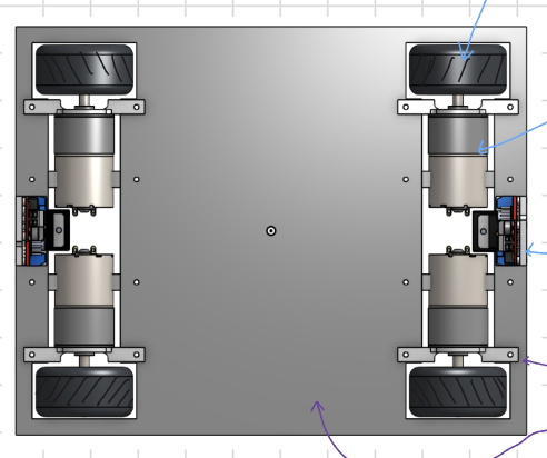
Drivetrain and Frame
4-wheel mecanum layout for holonomic movement and fast lateral correction.
200 RPM, 12V DC motors selected as a cost/performance balance.
L298N motor drivers with an XL6019 boost stage for robust supply overhead.
3D-printed motor mounts integrated into an aluminum frame.
The frame is optimized for predictable straight-line motion and fast reset between repeated shooting loops.
Shooter and Piece Handling
Flywheel launcher maintains wheel speed between shots for quick bursts.
Reload path keeps game pieces close to the ground for stable feed-in.
Shooter wheel and feed mechanism are tuned for repeated multi-piece firing.
Final build uses timed shooter/feed sequencing during each firing pass.
The mechanism is tuned for consistent release timing while the robot runs the same shot loop repeatedly.
Autonomy, Sensors, and State Machine
Two ultrasonic sensors estimate X/Y position from known arena walls.
IMU used to hold heading and reduce drift during straight-drive segments.
Shot timing is command-driven while navigation relies on ultrasonic + IMU.
State machine includes LOOP_WAIT for timed restarts and stops after 3 loops.
Motion and shooter actions are coordinated by defined state-machine steps, with heading hold and sensor-guided positioning.
Final Arduino Code (Implemented)
The final firmware runs a fire-only routine with timed firing, 10-second loop waits, and a 3-loop cap.
Core libraries: Wire, Adafruit_PWMServoDriver, MPU6050_light.Motor control: all drivetrain + shooter PWM routed through PCA9685 channels.Sensors: two ultrasonic sensors (right/back), MPU6050 yaw hold, quadrature shooter encoder.Shooter control: PID loop with KP=0.2, KI=0.8, KD=0.005.
Main setpoints: RIGHT_SETPOINT=25cm, BACK_SETPOINT=160cm.Home setpoints: HOME_RIGHT_SETPOINT=75cm, HOME_BACK_SETPOINT=4cm.Shot alignment: SHOOT_ANGLE=-60deg, ANGLE_TOLERANCE=3deg.Shooter command: ramp during strafe using SHOOTER_START(185) + SHOOTER_REDUCE * elapsed.Loop control: LOOP_WAIT waits 10s and restarts until loopCount == 3.
View Final Loop Flow from Code
Boot + Setup
Initialize MPU6050, calibrate offsets, configure PCA9685 (1 kHz), attach encoder interrupts.
Loop Align
INITIAL_ROTATE ->
DRIVE_BACK_TIMED ->
STOP_AND_ZERO ->
SPIN_180.
Setpoint + Shoot
DRIVE_TO_SETPOINT ->
TURN_TO_SHOOT_ANGLE ->
SPIN_UP_SHOOTER ->
SHOOT_AND_STRAFE.
Reset + Loop Wait
ROTATE_TO_ZERO ->
DRIVE_HOME ->
DONE ->
LOOP_WAIT(10s) ->
DRIVE_TO_SETPOINT.
Stop Condition
After
loopCount >= 3, the robot remains stopped in
LOOP_WAIT.
Loop Timing Plan
Baseline motion estimate remains ~4 seconds per travel leg at approximately 0.5 m/s.
Loop Step 1
Align and drive to the shoot setpoint using ultrasonic + IMU heading hold.
Loop Step 2
Turn to shooting angle, spin up flywheel, and strafe while firing pucks.
Loop Step 3
Rotate back to zero heading and drive home/reset.
Loop Step 4
Wait 10 seconds in
LOOP_WAIT, then restart from
DRIVE_TO_SETPOINT.
End Condition
Complete 3 loops total, then stay stopped.
Key Calculations and Validation Checks
Quick calculations used to confirm the routine would fit timing and positioning constraints.
Travel Leg Time
d = 67 in = 1.70 m, v ~= 0.50 m/s, t = d / v ~= 3.4 s
This set the baseline expectation for each outbound/inbound translation segment.
Loop Duration Budget
t_loop ~= (2 x 3.4 s) + 2.5 s firing + 10 s LOOP_WAIT ~= 19.3 s
Three loops target roughly 58 seconds, leaving margin for transient correction and startup.
Back Setpoint Conversion
BACK_SETPOINT = 160 cm ~= 63 in (near 67 in hog-line reference)
This helped tie in-code units to field measurements made during setup.
Shot Angle Window
SHOOT_ANGLE = -60 deg with ANGLE_TOLERANCE = +-3 deg (6 deg total window)
Small heading window improved consistency without over-constraining turn completion time.
Parts and Costs
HiPicco FR6ZZ flanged ball bearings (10 pcs) - $13.08 (order placed February 27, 2026;
single-item total).
Teyleten BTS7960 43A H-bridge motor driver (2 pcs) - Included in $53.44 order total
(order placed February 22, 2026).
12V 775 DC motor with bracket - Included in $53.44 order total (order placed
February 22, 2026).
CHANCS 20PPR AB hall encoder for 775 motor - Included in $53.44 order total
(order placed February 22, 2026).
Greartisan 12V 200 RPM gear motor (qty 3) - $46.52 (order placed February 21, 2026;
single-line order).
Greartisan 12V 200 RPM gear motor - Included in $81.78 order total (order placed
February 20, 2026).
L298N dual H-bridge motor driver boards (2 pcs) - Included in $81.78 order total
(order placed February 20, 2026).
Premium mecanum wheels (60 mm, 4 pcs) - Included in $81.78 order total (order
placed February 20, 2026).
XL6019 DC-DC boost converters (3 pcs) - Included in $81.78 order total (order
placed February 20, 2026).
3A mini buck converters (10 pcs) - Included in $81.78 order total (order placed
February 20, 2026).
Treedix IR break-beam sensors (qty 2) - Included in $56.18 order total (order
placed February 17, 2026).
HC-SR04 ultrasonic sensors (2 pcs) - Included in $56.18 order total (order placed
February 17, 2026).
PMW3901 optical flow sensor module - Included in $56.18 order total (later refunded)
(order placed February 17, 2026).
GY-521 MPU6050 IMU modules (3 pcs) - Included in $56.18 order total (order placed
February 17, 2026).
Reflections and Advice for Next Year
Most valuable takeaway: integrated reliability beats isolated subsystem performance. Build around repeatability first.
What Worked Well Together
Mecanum mobility plus IMU heading hold made reset and re-entry paths highly repeatable.
Wall-referenced ultrasonic setpoints reduced dependence on wheel odometry under slip.
State-machine structure made debugging faster by isolating failures to specific phases.
Integration Challenges
Encoder hardware damage forced a late-stage control-plan change.
Concurrent drive, sensing, and shooter timing created intermittent edge-case drift.
Power and wiring noise required careful routing and grounded debugging habits.
Arduino and Library Debug Tricks
Use millis()-based timers instead of long blocking delay() calls in autonomous logic.
Apply deadbands around ultrasonic targets to prevent oscillation near setpoints.
Clamp and sanity-check sensor readings before feeding them into control decisions.
Track per-state entry timestamps so each phase can be tuned and logged independently.
Suggestions to Future Teams
Lock MVP behavior by mid-build and treat extra features as optional until consistency is proven.
Keep one known-good autonomous routine always runnable while you test new ideas on a branch path.
Capture build photos/video every week; those records are invaluable for handoff and troubleshooting.
Budget time for integration-only days, not just subsystem bring-up days.